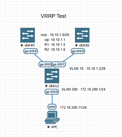
주니퍼 스위치 VRRP(Virtual Router Redundancy Protocol) 설정하기.
* 작업환경:
eve-ng 커뮤니티 버전, 주니퍼 vEX 스위치.
* 구성 : 아래 그림과 같이 시험환경 구성.
1. 스위치1, 스위치2의 vrrp 설정.
1.1. R1 스위치 설정
L2 스위치와 연결된 인터페이스에 IP 주소와 VRRP설정을한다.
[edit]
root# set interfaces ge-0/0/0 unit 10 family inet address 10.10.1.5/29 vrrp-group 10 virtual-address 10.10.1.1 priority 250 accept-data
1.2. R2 스위치 설정
L2 스위치와 연결된 인터페이스에 IP 주소와 VRRP설정을한다. backup 라우터로 작동하기 위해 우선순위를 200 으롤 낮추었다.
[edit]
root# set interfaces ge-0/0/0 unit 0 family inet address 10.10.1.6/29 vrrp-group 10 virtual-address 10.10.1.1 priority 200 accept-data
2. L2 스위치 설정
R1, R2 스위치와 연결하기위해 VLAN을 설정한다.
[edit]
root# set vlans V10 vlan-id 10
각 스위치와 연결된 포트에 VLAN을 설정한다.
[edit]
root# set interfaces ge-0/0/0 unit 0 family ethernet-switching vlan members V10
[edit]
root# set interfaces ge-0/0/1 unit 0 family ethernet-switching vlan members V10
VLAN 인터페이스에 IP 주소를 설정한다.
[edit]
root# set interfaces irb unit 10 family inet address 10.10.1.2/29

[edit]
root# set vlans V10 l3-interface irb.10
3. VRRP 동작 확인.
여기까지 설정 후, R1, R2 스위치에서 vrrp 상태를 확인 해 본다.
R1에서 vrrp 확인 : master 라우터로 작동중
root> show vrrp
Interface     State       Group   VR state VR Mode   Timer    Type   Address
ge-0/0/0.0    up             10   master   Active      A  0.021 lcl    10.10.1.5
                                                                vip    10.10.1.1
R2에서 vrrp 확인 : backup 라우터로 작동중
root> show vrrp
Interface     State       Group   VR state VR Mode   Timer    Type   Address
ge-0/0/0.0    up             10   backup   Active      D  2.847 lcl    10.10.1.6
                                                                vip    10.10.1.1
                                                                mas    10.10.1
L2 에서 각 라우터까지 ping 확인
root> ping count 1 10.10.1.1
PING 10.10.1.1 (10.10.1.1): 56 data bytes
64 bytes from 10.10.1.1: icmp_seq=0 ttl=64 time=2.191 ms

root> ping count 1 10.10.1.5
PING 10.10.1.5 (10.10.1.5): 56 data bytes
64 bytes from 10.10.1.5: icmp_seq=0 ttl=64 time=2.335 ms

--- 10.10.1.5 ping statistics ---
1 packets transmitted, 1 packets received, 0% packet loss
round-trip min/avg/max/stddev = 2.335/2.335/2.335/0.000 ms

root> ping count 1 10.10.1.6
PING 10.10.1.6 (10.10.1.6): 56 data bytes
64 bytes from 10.10.1.6: icmp_seq=0 ttl=64 time=1.918 ms

--- 10.10.1.6 ping statistics ---
1 packets transmitted, 1 packets received, 0% packet loss
round-trip min/avg/max/stddev = 1.918/1.918/1.918/0.000 ms
4. VPC에서 각 라우터까지 통신확인.
L2에 vpc가 사용할 VLAN 만들고, 기본게이트웨이를 설정한다.
[edit]
root# set interfaces irb unit 200 family inet address 172.16.200.1/24

[edit]
root# set vlans DATA l3-interface irb.200

[edit]
root# set interfaces ge-0/0/9 unit 0 family ethernet-switching vlan members DATA

[edit]
root# set routing-options static route 0.0.0.0 next-hop 10.10.1.1
R1, R2에 각각 vpc(172.16.200.0/24)로 라우팅되도록 static 라우팅을 설정해둔다.
[edit]
root# set routing-options static route 172.16.200.0/24 next-hop 10.10.1.2
vpc에서, 각 라우터까지 ping으로 통신 확인
VPCS> show ip

NAME        : VPCS[1]
IP/MASK     : 172.16.200.11/24
GATEWAY     : 172.16.200.1
DNS         :
MAC         : 00:50:79:66:68:04
LPORT       : 20000
RHOST:PORT  : 127.0.0.1:30000
MTU         : 1500
R1, R2의 IP 주소로 ping 테스트.
VPCS> ping 10.10.1.5 -c 1

84 bytes from 10.10.1.5 icmp_seq=1 ttl=63 time=1.197 ms

VPCS> ping 10.10.1.6 -c 1

84 bytes from 10.10.1.6 icmp_seq=1 ttl=63 time=1.502 ms
* 필요에 따라, R1-R2사이에 인터링크를 설정한다. 여기서는 테스트이므로 생략!

